 Buffer
| Library: |
Gates |
| Introduced: |
2.0 Beta 1 |
| Appearance: |
 |
Behavior
The buffer simply passes through to its right output whatever input
it receives on the left side.
The truth table for a one-bit buffer is the following.
If the input is unspecified (i.e., floating), then the output will also be
unspecified - unless the "Gate Output When Undefined" option is "Error for
undefined inputs," in which case the output is an error. If the input is an
error value, then the output will also be.
Buffers are the most useless of the gate components
provided in Logisim; its presence in the Gates library is just as much a
matter of completeness (a component for each possible
one-input truth table) as it is a matter of providing useful
functionality. Still, it can be occasionally useful to ensure that
values propagate in only one direction along a wire.
Pins (assuming component faces east)
- West edge (input, bit width according to Data Bits property)
- The input into the component.
- East edge (output, bit width according to Data Bits property)
- The output, which always matches the input into the left side.
Properties
When the component is selected or being added,
Alt-0 through Alt-9 alter its Data Bits
property
and the arrow keys alter its Facing
property.
- Facing
- The direction of the component (its output relative to its input).
- Data Bits
- The bit width of the component's inputs and outputs.
- Output Value
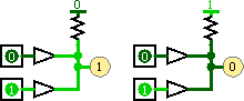
- Indicates the set of possible outputs. When "0/1" is selected, both 0 and 1
are possible outputs and the component behaves according to the table above.
When "0/floating" is selected, the component will output a floating X value
whenever it would normally output a 1. Similarly, when "floating/1" is selected,
the component will output a floating X value whenever it would normally output
a 0. The floating output options allow for wired-or and wired-and connections,
as illustrated below: At left, the Buffers' Output Value properties are floating/1
and the resistor pulls to 0, giving wired-or behavior; at right, the Buffers'
Output Value properties are 0/floating and the resistor pulls to 1, giving
wired-and behavior.
- Label
- The text within the label associated with the gate.
- Label Font
- The font with which to render the label.
Poke Tool Behavior
None.
FPGA Synthesis
All basic gates support VHDL and Verilog synthesis.
Floating outputs (selected with 'Output Value' property) are not supported for
synthesis.
Up to Library Reference